Beams - Forces
When the model is solved, the results are separated into specific design results and generic results. This section discuss the generic beam forces results. The design results are discussed in Beams - Design Results.
Number of Reported Sections
Note that the beam forces are only reported at the section locations. For example, if you set the Number Of Reported Sections in the Model Settings dialog to '2', you will not get any results for the middle of your beam, you will only get results for the end points. If you have a point load applied to your member at a location that is not a section location, you will probably not report the maximum moment in the section if it does not occur at an endpoint.
Adjust Number of Sections
To adjust the number of Sections:
- Go to the Model Settings window.
- If not already open, click on the Solution tab.
-
Adjust the Number of Reported Sections as needed.
Note: Adjusting the number of sections affects the amount of output.
Number of Internal Sections
Internally, the program subdivides the beam into equally spaced sections to calculate forces, code checks, etc. The Number of Internal Sections can be adjusted in the Model Settings dialog. If this value were set to '100', this would mean that for a beam that is 100ft long, RISAFoundation will calculate these values at approximately every foot. These values are then used in the beam code checks, diagrams in the model view and detail reports. The locations of the maximum code checks are reported at a distance from the Start Point.
Adjust Number of Internal Sections
To adjust the number of internal Sections:
- Go to the Model Settings window.
- If not already open, click on the Solution tab.
- Adjust the Number of Internal Sections as needed.
All other results are reported at the Number of Reported Sections that you specify in the Model Settings dialog. This controls how many places you receive reported or printed beam force results. These locations are also equally spaced, so setting the value to '5' will give you 5 equally spaced sections; at the ends, the middle and the quarter points.
- Adjusting the Number of Internal Sections will not affect the amount of output in the results spreadsheets.
- You may want to stick with odd numbers for the Number of Reported Sections. Setting the Number of Reported Sections to an even number will not report forces at the midpoint of the beam, which is often the location of maximum moment.
Beam Force Results
Access the Beam Section Forces spreadsheet by going to the Results menu and selecting Beam Forces.

Click on image to enlarge it
These are the beam forces calculated along each beam. The units for the forces are shown at the top of each column. As for the sign convention, the signs of these results correspond to the beam's local axes, using the right hand rule. The left side forces at each section location are displayed. There are three force values for each section location.
These include shear parallel to the local y-axis (y Shear), torque moment and moment about the member's local z-axis ( z-z Moment).
These section forces may also be displayed graphically. Remember that the section forces used for the plot are the left side forces. For an example of what you would see for the graphic plot of the moment diagram for a member, please see below:
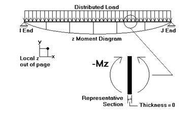
RISAFoundation uses the right hand rule joint convention and is always consistent with this convention. Since the left side moment is being used, a beam under negative Mz moment would have the "holds water" deflected shape, which is contrary to some beam conventions. The opposite is true for My moments which will tend to "hold water" under a positive moment and "shed water" under a negative moment.
- To learn how to use Find, Sort and other options, see Spreadsheet Operations.
- To learn how to plot beam results, see Beams.